Hardware design decisions
Microcontroller
I needed an Arduino-compatible microcontroller with sufficient (see Multiplexing) analog inputs. Additionally, I wanted it to be relatively small.
ATmega32U4-based microcontrollers have the additional advantage of being able to simulate a HID such as a keyboard, making it possible to type moves without needing a program that runs on the PC. (This is not implemented yet, but it’s nice to have the option for the future.)
I chose a SparkFun Pro Micro clone because it fulfilled my requirements and I had some available.
Sensor
I needed a cheap sensor that could reliably determine whether a square was occupied. I considered the following sensor types:
| Type | Pieces needed | disadvantages |
|---|---|---|
| Induction sensors | weighted | relatively expensive |
| Hall sensors | magnetic | needs more complex wiring |
| Reed switches | magnetic | |
| Photoresistors | any | can’t be “hidden”, potentially prone to lighting conditions |
I elected to use photoresistors because I was able to get them cheaply in large quantity (14€ for 350pcs) without a multiple-month delivery time.
Any of the sensors metioned should work well, however.
Multiplexing
LiBoard uses a photoresistor in each square in order to determine which squares are occupied. Each photoresistor needs to be connected to 5 V and an analog input.
Because wiring each photoresistor to an individual input would need more inputs than commonly available and would result in messy wiring, the photoresistors should be multiplexed:
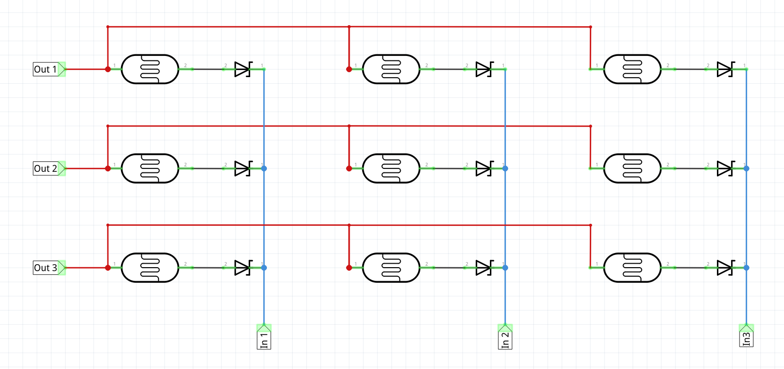 Due to the layout of a chessboard, 8x8 multiplexing is the most natural way. However, if fewer than 8 analog inputs are available, one should be able to do 16x4 multiplexing without too much difficulty.
Shift-register
I chose to use a serial-in parallel-out (SIPO) shift register to reduce the number of outputs needed. I used a SN74HC595N, but there should be plenty of alternatives.
The advantage of shift registers is that they’re cheap and only need two digital outputs (data and clock) to work. It’s also possible to daisy-chain multiple shift registers, making 16x4 multiplexing possible with just 2 digital outputs.
Having unused digital outputs can come in handy if one decides to add more hardware (such as an LCD) to the board.
However, shift registers require a bit of circuitry and one can easily build a working board without them. It’s just a matter of connecting the board directly to the microcontroller’s digital outputs and changing the Arduino code a bit.
The diodes after the shift register (see circuit diagram) are not strictly necessary.
Pull down resistors
The inputs need to be connected to a pull-down resistor in order to work properly. I used 100 kΩ resistors, because I found them to result in the best readings in combination with the photoresistors I used.